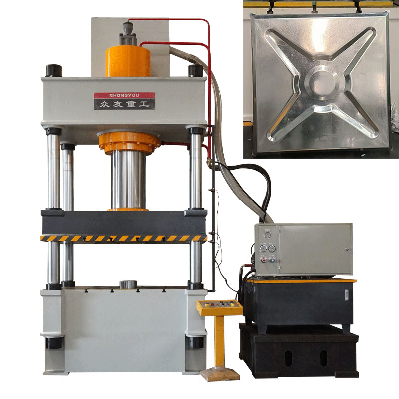
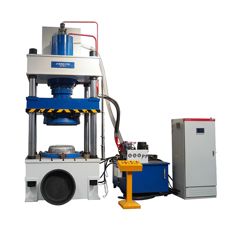
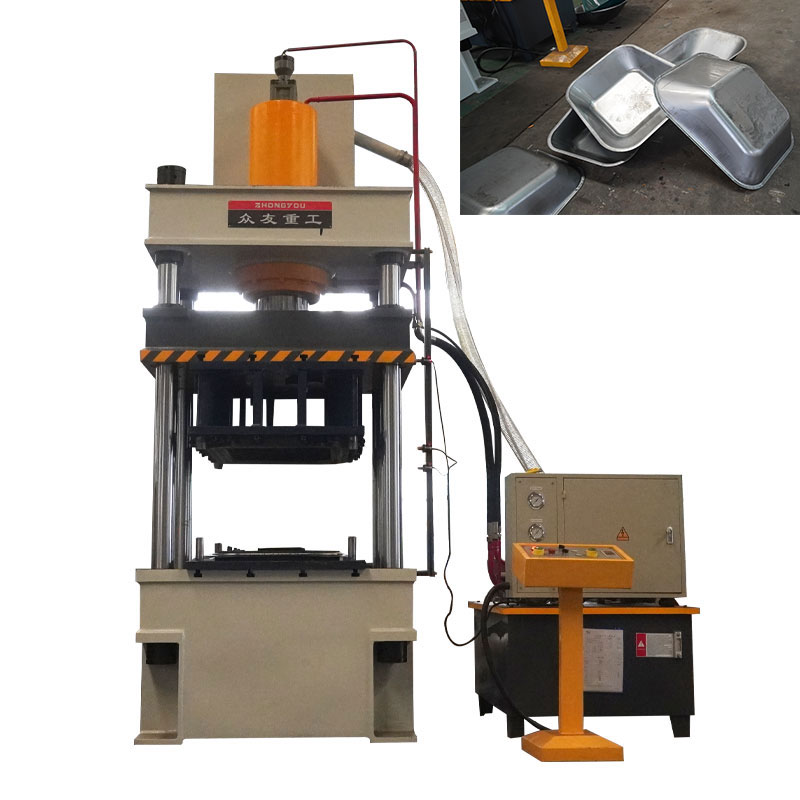
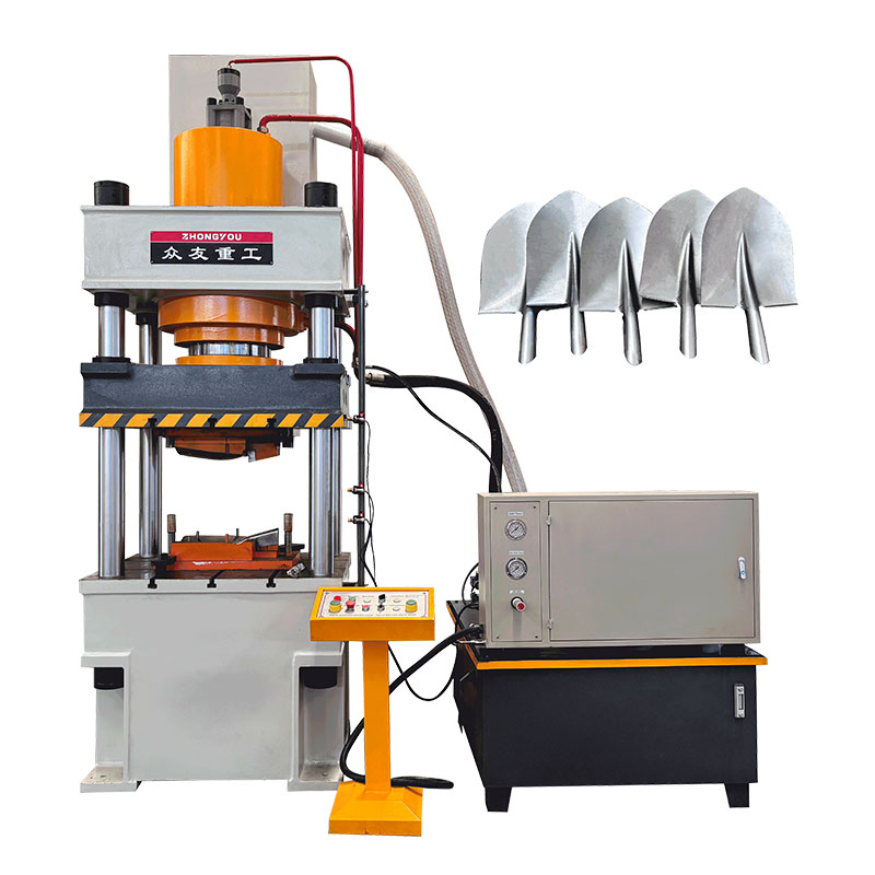
315 tons of molded glass fiber reinforced plastic water tank hydraulic press
Shandong Zhongyou Heavy Industry has customized a FRP water tank press for Taizhou customers. It is a hydraulic equipment specially designed for glass fiber reinforced plastic (FRP) water tank forming. It is mainly used to apply resin-impregnated glass fiber layers (or other reinforcing materials) in the mold. Pressure and cure, and finally form a water tank structure with high strength and corrosion resistance.

Scan code plus WeChat
+86 13562463338

+86 13562463338
Video Show
Introduction of hydraulic press
Due to its advantages of light weight, corrosion resistance, leakage resistance, and long life, FRP water tanks are widely used in fire protection, water treatment, building water supply and drainage, industrial liquid storage and other fields. The key to its forming is to apply uniform pressure to the fiber layer through a press to eliminate bubbles in the resin, promote the resin curing reaction, and ensure the structural strength and tightness of the water tank.
The core functions of the FRP water tank press are:
Provide constant pressure to make the fiber layer closely adhere to the mold;
Control pressing timing and holding time (match resin curing process);
Mold compatibility to adapt to different size water tanks (e.g. round, square water tanks)
application scenarios
FRP water tank presses are mainly used to produce the following types of water tanks:
Fire water tank: used for building fire protection systems,
Domestic drinking water tanks: used in communities, hotels, and schools, requiring non-toxic and corrosion-resistant (food grade resin);
Industrial liquid storage tank: Storage of corrosive liquids in the chemical and pharmaceutical industries (acid and alkali resistant resin is required);
Modular combined water tank: Multiple standard modules are spliced, and the press can be adapted to small size molds to achieve mass production.
GEO-CANARY-86EA1707
Technical parameters
| YQ32 series three-beam four-column hydraulic press | |||||||
| project | 100T-A | 100T-B | 160T | 200T-A | 200T-B | 315T-A | 315T-B |
| Liquid pressure Mpa | 25 | 25 | 25 | 25 | 25 | 25 | 25 |
| Effective stroke of slider mm | 500 | 600 | 600 | 700 | 600 | 800 | 600 |
| Opening height mm | 800 | 900 | 900 | 1200 | 900 | 1250 | 1000 |
| Effective area of workbench | 630*550 | 750*700 | 660*600 | 1000*1000 | 800*800 | 1260*1160 | 800*800 |
| Idle descent speed mm/s | 100 | 100 | 100 | 100 | 100 | 120 | 120 |
| Pressing speed mm/s | 7-15 | 7-15 | 7-15 | 7-18 | 7-18 | 7-12 | 7-12 |
| Return speed mm/s | 90 | 90 | 90 | 90 | 90 | 100 | 90 |
| Motor power KW | 5.5 | 5.5 | 7.5 | 7.5 | 7.5 | 22 | 15 |
| Jacking force KN | 200 | 200 | 400 | 400 | 400 | 630 | 630 |
| Ejecting stroke mm | 200 | 200 | 200 | 200 | 200 | 300 | 300 |
| YQ32 series three-beam four-column hydraulic press | |||||||
| project | 400T | 500T | 630t | 800T | 1000T | 1250t | 1600t |
| Liquid pressure Mpa | 25 | 25 | 25 | 25 | 25 | 25 | 25 |
| Effective stroke of slider mm | 800 | 900 | 900 | 1000 | 900 | 900 | 1000 |
| Maximum opening height mm | 1250 | 1500 | 1500 | 1800 | 1600 | 1600 | 1800 |
| Effective area of workbench | 1260*1160 | 1400*1400 | 1600*1600 | 1500*1500 | 1500*1500 | 1800*1600 | 1600*1600 |
| Idle descent speed mm/s | 100 | 150 | 150 | 180 | 180 | 160 | 180 |
| Pressing speed mm/s | 5-11 | 10-18 | 9-18 | 9-18 | 10-18 | 10-18 | 6-14 |
| Return speed mm/s | 100 | 120 | 150 | 180 | 220 | 200 | 220 |
| Motor power KW | 45 | 45 | 45 | 37*2 | 37*2 | 37*2 | 37*2 |
| Jacking force KN | 630 | 1000 | 1000 | 1000 | 1000 | 1000 | 1600 |
| Ejecting stroke mm | 300 | 300 | 300 | 300 | 300 | 300 | 350 |
pressing process

Suppression case

Technical parameters
| YQ32 series three-beam four-column hydraulic press | |||||||
| project | 100T-A | 100T-B | 160T | 200T-A | 200T-B | 315T-A | 315T-B |
| Liquid pressure Mpa | 25 | 25 | 25 | 25 | 25 | 25 | 25 |
| Effective stroke of slider mm | 500 | 600 | 600 | 700 | 600 | 800 | 600 |
| Opening height mm | 800 | 900 | 900 | 1200 | 900 | 1250 | 1000 |
| Effective area of workbench | 630*550 | 750*700 | 660*600 | 1000*1000 | 800*800 | 1260*1160 | 800*800 |
| Idle descent speed mm/s | 100 | 100 | 100 | 100 | 100 | 120 | 120 |
| Pressing speed mm/s | 7-15 | 7-15 | 7-15 | 7-18 | 7-18 | 7-12 | 7-12 |
| Return speed mm/s | 90 | 90 | 90 | 90 | 90 | 100 | 90 |
| Motor power KW | 5.5 | 5.5 | 7.5 | 7.5 | 7.5 | 22 | 15 |
| Jacking force KN | 200 | 200 | 400 | 400 | 400 | 630 | 630 |
| Ejecting stroke mm | 200 | 200 | 200 | 200 | 200 | 300 | 300 |
| YQ32 series three-beam four-column hydraulic press | |||||||
| project | 400T | 500T | 630t | 800T | 1000T | 1250t | 1600t |
| Liquid pressure Mpa | 25 | 25 | 25 | 25 | 25 | 25 | 25 |
| Effective stroke of slider mm | 800 | 900 | 900 | 1000 | 900 | 900 | 1000 |
| Maximum opening height mm | 1250 | 1500 | 1500 | 1800 | 1600 | 1600 | 1800 |
| Effective area of workbench | 1260*1160 | 1400*1400 | 1600*1600 | 1500*1500 | 1500*1500 | 1800*1600 | 1600*1600 |
| Idle descent speed mm/s | 100 | 150 | 150 | 180 | 180 | 160 | 180 |
| Pressing speed mm/s | 5-11 | 10-18 | 9-18 | 9-18 | 10-18 | 10-18 | 6-14 |
| Return speed mm/s | 100 | 120 | 150 | 180 | 220 | 200 | 220 |
| Motor power KW | 45 | 45 | 45 | 37*2 | 37*2 | 37*2 | 37*2 |
| Jacking force KN | 630 | 1000 | 1000 | 1000 | 1000 | 1000 | 1600 |
| Ejecting stroke mm | 300 | 300 | 300 | 300 | 300 | 300 | 350 |
pressing process
Suppression case